Stress testing printed parts
November 1, 2026
A 3D printed bracket or a machined robot link has to carry its load without bending permanently or snapping. Static stress analysis with the finite element method checks that in software before the part is made. It splits a CAD part into thousands of small tetrahedral elements, applies the supports and forces the part will see in use, and computes how far the shape bends and where internal stress builds up around holes, thin walls and inside corners.
This article explains how finite element stress analysis works, how peak stress is compared against a material's yield strength to get a safety factor, and how a stress test is set up and read on a FloMotion test bench. In FloMotion, a test bench attaches to a CAD assembly, meshes the chosen part or subassembly on the server and solves the load case. The result shows a colour map of the stress and the bent shape, exaggerated to make it visible. An AI agent can set up a test from a question, read where the peaks are and suggest CAD edits that strengthen or lighten the part.
Beam formulas, proof tests and finite elements
A mechanical part is sized so that the stress inside it stays below what its material can take. On the workbench the question is usually plain: does this bracket hold the motor, or does this arm snap when the robot falls over?
Hand formulas from Euler-Bernoulli beam theory, worked out in the 18th century, give a quick answer for simple shapes. Real parts have bolt holes, fillets and ribs where those formulas stop working. The other classic check is proof testing on a rig: printing or machining the part and loading it until it breaks. That gives a sure answer, at the cost of a part and a day per try.
A third way is to split the shape on a computer into thousands of small pieces whose stiffness is known and solve them together. In 1943 Richard Courant solved a torsion problem by splitting its region into small triangles with a simple guess on each. In 1956 Turner, Clough, Martin and Topp at Boeing published Stiffness and Deflection Analysis of Complex Structures, applying the idea to aircraft frames. Ray Clough named it the finite element method in 1960, and NASA's NASTRAN program brought it into general engineering use in the late 1960s. Today finite element analysis (FEA) is a standard check before a part is made, in aerospace, cars and consumer products.
How finite element stress analysis works
A stress solver starts by splitting the part's volume into many small tetrahedra. That collection of elements is the mesh. Each element acts like a small spring whose stiffness follows from the material's Young's modulus and Poisson's ratio. The solver takes which faces are held still and which faces carry a load, and finds how far every corner of every tetrahedron moves so that all forces balance. The stress in each element follows from how much it is stretched.
Inside a loaded part, material is pulled, pushed and sheared in three dimensions at once. Von Mises stress, named after Richard von Mises who formulated it in 1913, combines that three-dimensional state at a point into a single number. That number is compared with the material's yield strength, the stress at which the material starts to deform permanently.
The safety factor is the yield strength divided by the highest von Mises stress in the part. At a safety factor under 1, the part yields. Designers often aim for 1.5 to 2 or more, because loads, prints and materials vary.
Stress does not spread evenly. It gathers at inside corners, around holes and across thin walls, an effect called stress concentration. Adding a fillet at a sharp inside corner or thickening a wall spreads the load and lowers the peak.
The test bench
In FloMotion, stress tests live in a test bench. A test bench is a project item tied to one CAD assembly in the same project. It holds any number of experiments, where each experiment is one test of one subject: a single part, a subassembly, or the whole assembly.
A test bench is created from the project page with New → Test bench by picking the assembly, or by asking the AI. From an open CAD workspace the agent can create one directly from a prompt such as test whether this bracket holds 3 kg.
On desktop, the subject in 3D fills the left of the page. The panel on the right shows one of three views, picked from a rail at the far right: the Experiments list with the setup of the open experiment, the Result, or the AI panel. On a phone the same parts are arranged as tabs: Experiments, Viewport, Result and AI.
Setting up a stress test
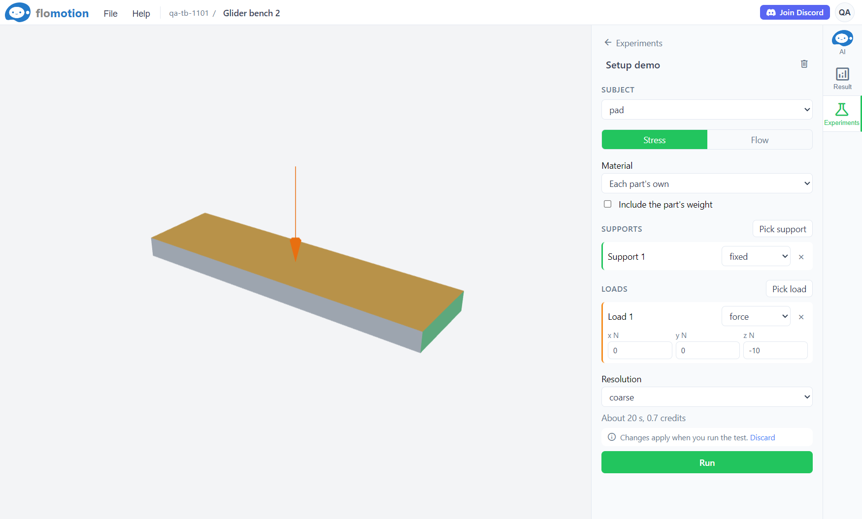
A stress test needs a subject, at least one support, at least one load, a material and a mesh setting.
- Subject. Pick a single part or a subassembly from the assembly tree. Parts that touch in a chosen subassembly are joined into one solid, as if glued together.
- Supports. Click Pick support, then click the face the part is held by in the viewport. A single click picks the whole CAD face, whether that is a flat mounting face, a cylindrical bore or a fillet. A fixed support holds the face in every direction; a sliding support only stops movement through the face.
- Loads. Click Pick load, then click the face the load acts on. A load is either a force in newtons given by its
x,yandzcomponents, spread over the face by area, or a pressure in MPa pushing normal to the face. - Material. The test can use each part's own material from the assembly (PLA, PETG, ABS, plywood, aluminium or steel), or apply one material to all parts in the test. A part that has no material set in the assembly counts as PLA, and the result notes that.
- Gravity. Checking Include the part's weight adds gravity to the load.
- Mesh. The mesh can be quick or accurate. Both size the elements from the part itself, letting them shrink to half the thickness of the thinnest wall on quick and a third on accurate, within caps of 100,000 and 600,000 second-order tetrahedra. Typical run times on the server are about 30 seconds and 3 minutes. The panel shows the typical time and the cost in credits before the run starts. Quick is useful for trying setups, and accurate is for the final number.
Run sends the part to the server. The server meshes it into second-order tetrahedra with Gmsh, an open-source mesh generator by Christophe Geuzaine and Jean-François Remacle. CalculiX, an open-source finite element solver by Guido Dhondt and Klaus Wittig, then solves it as a linear static problem. The page shows progress while the solver works, and a run can be cancelled at any point.
Edits to the setup stay as a draft until the next run, so the result on the page always belongs to the setup shown next to it. A result stays on screen after the CAD part or the setup changes, marked as older than the setup until the experiment runs again.
Reading the result
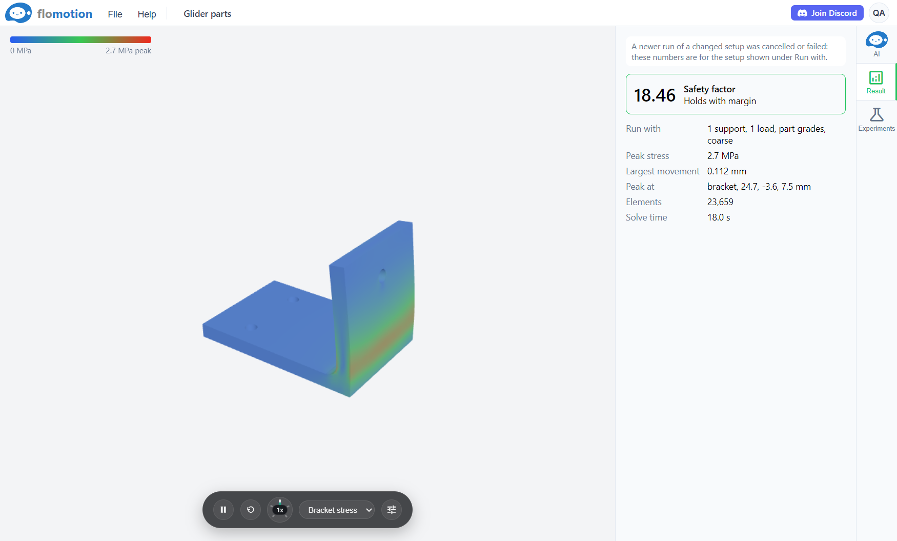
The finished result colours the part in the viewport from blue at zero stress through green to red, with a legend in MPa. The Colour up to setting scales the red end of the bar either to the Peak stress in the part or to the material's Yield strength. Hovering over the part reads the stress and movement at that point.
The result panel lists the safety factor, the peak von Mises stress and where it sits, the largest movement in millimetres, the number of elements, the solve time, and the conditions the test ran with.
In the Test bench demos project, the PLA wing bracket is held fixed at its mounting face and loaded with 30 N backwards and 8 N down on the wing face. A quick run uses 23,659 elements and solves in 18 seconds. The peak von Mises stress is 2.7 MPa, the largest movement is 0.11 mm, and the safety factor is 18.5. The stress is far below yielding, so the part has plenty of margin and could be made lighter.
Real movements under working loads are often a fraction of a millimetre and hard to see at true scale. The Deformation slider exaggerates the bend up to 50 times, and the playback bar animates the part swinging between its rest shape and its bent shape so it is clear how the load flexes the structure.
The agent on the test bench
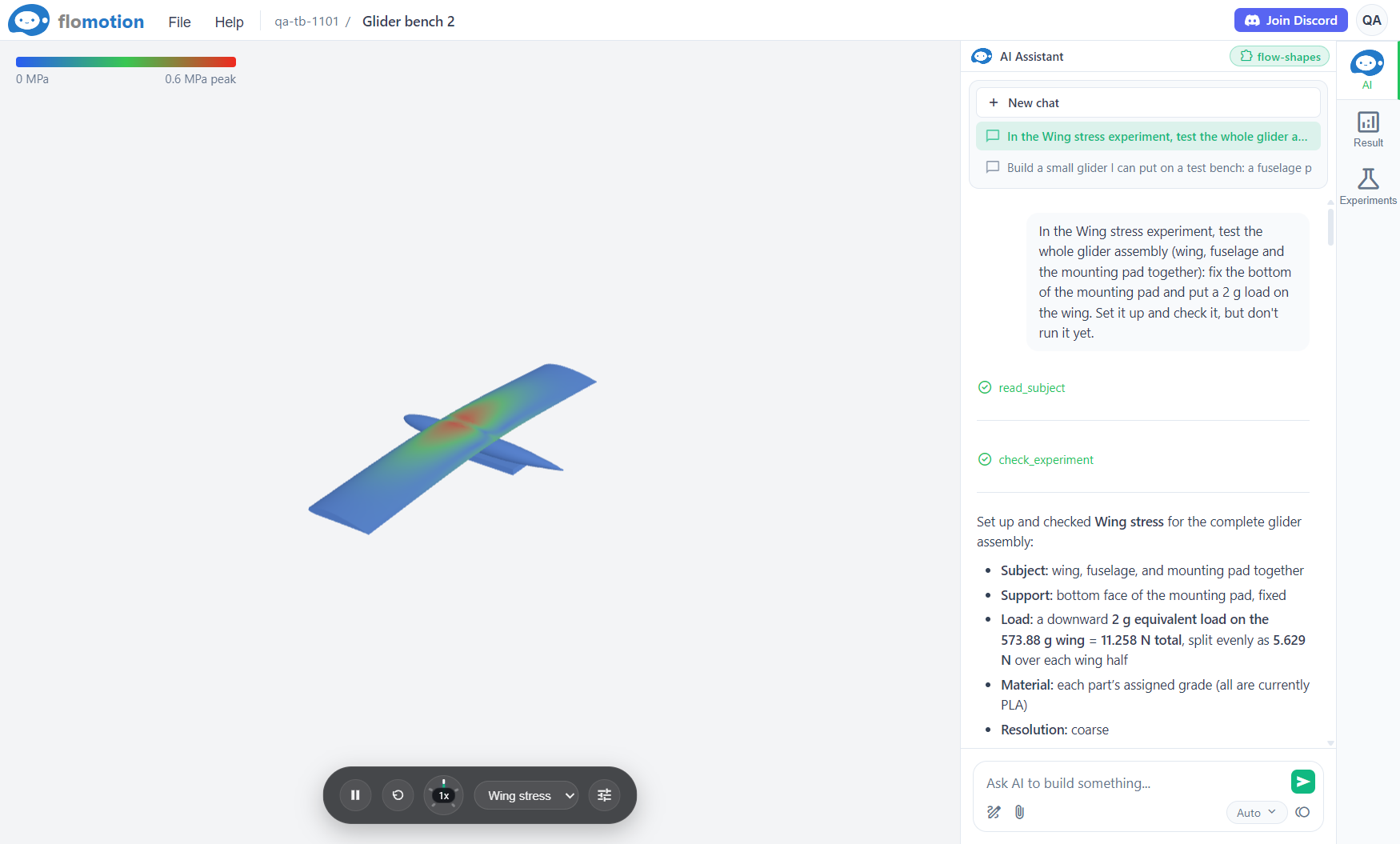
In the AI panel, a plain question becomes a test. Asking will this bracket hold 2 kg hanging from the hole? prompts the agent to read the part's faces, mass and material, set the supports and loads, and run a quick test first. It states the expected time and credit cost before starting an accurate run.
The agent then reads the finished result, points out where the peak stress sits and what would lower it, and can probe values at specific points or take screenshots of the coloured mesh. It can propose a design change, such as a fillet at a sharp inside corner where the peak sits. With agreement it goes back to the CAD workspace to make the edit, then reruns the test to compare.
The agent handles common setups well in practice, but it can pick the wrong face for a support or apply an unrealistic load. Checking the green and orange faces in the viewport before relying on the safety factor catches those mistakes early.
Cost
Stress runs are billed by the minute of server time at 0.5 credits per minute, drawn from the same credits used for the AI agent. A typical quick run takes about 30 seconds and costs 0.5 credits.
Limits
- The solver runs linear static analysis only: it assumes small deformations and a linear elastic material, and does not model plastic bending, contact between separate parts, buckling, fatigue or vibration.
- Materials are modelled as isotropic. In a 3D printed part, the bond between layers is weaker than the filament along a layer, so a part loaded in a direction that pulls its layers apart can fail below the stress the safety factor predicts.
- In a subassembly test, parts that touch are welded together as one solid rather than bolted or allowed to slide against each other.
- A quick mesh can under-resolve thin walls and sharp inside corners. An accurate run gives the final peak stress.
Summary
Finite element analysis estimates whether a part will hold a load by splitting its volume into small tetrahedra and solving for the movement and stress across all of them. On a FloMotion test bench, a stress experiment takes a part or subassembly from a CAD workspace, holds its mounting faces, applies forces or pressures to its loaded faces, and meshes and solves the problem on the server with Gmsh and CalculiX. The result shows the von Mises stress across the part, the safety factor against yielding, and the exaggerated deformation, and the agent can set up runs, read the peaks and suggest CAD changes to make the part stronger or lighter.
Links
Try it yourself
Open the workspace, describe a part, and see what the agent does with it. No install, no setup. Sign-in is optional for the first run.
Start building