AI agent generated 3D print
May 20, 2026
This guide covers the workflow from prompting an AI agent to a sliced 3D print. The example tool is FloMotion's CAD workspace, but the principles apply to any AI-driven CAD that exports STEP.
The basic loop
- Open a CAD workspace with an AI agent.
- Describe the part. Include the manufacturing context (3D print, target printer, clearances).
- Iterate by chat until the geometry is right.
- Export to STEP, open in your slicer, print.
The handoff point is the STEP file. Everything before that is CAD modelling; everything after is slicing and printing.
Writing the prompt
The agent treats your prompt as a spec. Vague prompts produce generic parts. Specific prompts produce useful ones. Include:
- Dimensions:
30×30×5mm,M3 holes on a 24mm pattern. - Manufacturing context:
for 3D printing,0.4mm nozzle,no support material. - Tolerances where they matter:
0.3mm clearance between mating parts,press-fit for a 6mm shaft.
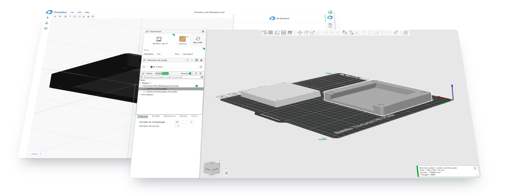
For example, a VESA 75-to-100 adapter plate starts with a prompt like:
A VESA 75 to 100 adapter plate, 5mm thick. Inner 75×75mm hole pattern with M4 clearance holes for the monitor side, outer 100×100mm hole pattern with M4 clearance holes for the arm side. For 3D printing.
Other example prompts that produce printable parts:
A print-in-place hinge for a 10mm wide flap, 0.3mm clearance between the pin and barrel.
A snap-fit lid for a 60×40×20mm enclosure, no screws.
If you don't mention 3D printing, the agent may pick features that are easy to machine but awkward to print (deep narrow slots, unsupported overhangs). Saying "for 3D printing" up front avoids re-work.
Iterating
Edits are incremental. The agent modifies the existing part rather than regenerating it. Common follow-ups:
Make the wall 0.4mm thicker so it prints solid at two perimeters.
Add a 45° chamfer to the bottom edges so it doesn't need a brim.
Move the screw holes 2mm inward.
Dimensions are preserved across edits unless you or the agent change them explicitly.
STEP versus STL
Slicers accept both. Pick based on what you plan to do later:
- STL is a triangulated mesh. Universal slicer support, but the geometry is no longer editable in a useful sense. Choose STL if the part is final and you only need to print it.
- STEP is parametric B-rep. Slicers that read it directly (PrusaSlicer 2.6+, SuperSlicer, Bambu Studio) generate cleaner slices on curves. The file stays editable in any CAD tool, including FloMotion, FreeCAD, Fusion 360, and OnShape.
For most workflows STEP is the safer export: you can always convert it to STL later, but not the other way around.
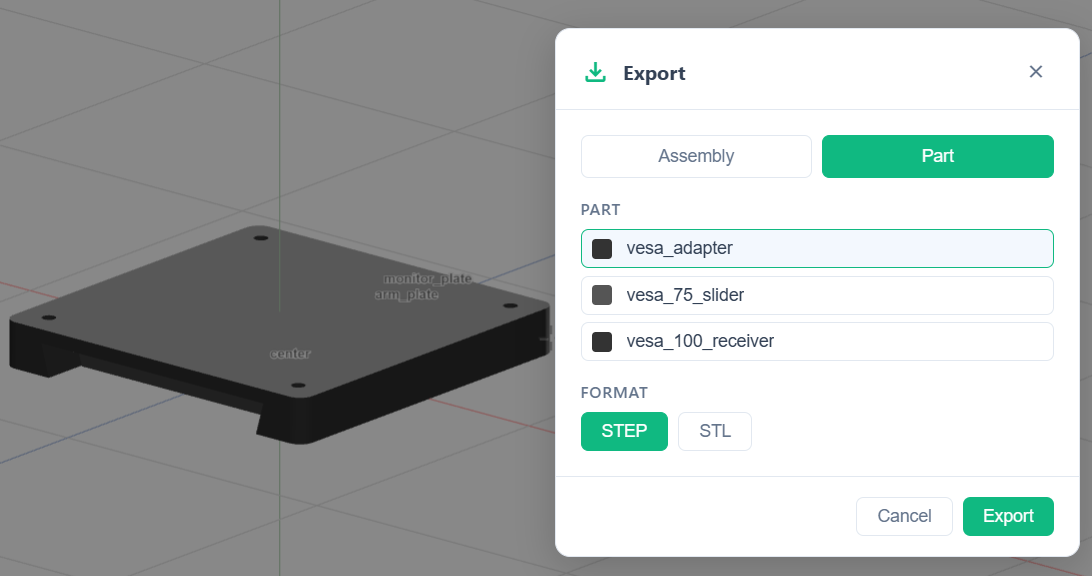
Exporting
In the workspace:
- Open the menu, choose Export.
- Pick STEP (
.step) or STL (.stl). - The file downloads. Drop it into your slicer.
Units are millimetres, which is the default in every common slicer.
What the agent is good at, and what it isn't
Reliable today:
- Brackets, mounts, plates with holes, enclosures, fixtures.
- Simple mechanisms: hinges, clips, snap-fits.
- Parts described with explicit dimensions and constraints.
Less reliable:
- Organic or sculpted shapes. Use a sculpting tool for those.
- Designs where aesthetics dominate. The agent optimises for fit and function, not visual style.
- Highly specific industry standards (medical, aerospace tolerances) without explicit references in the prompt.
Getting started
- Sign in and click Start Building.
- Create a project, then a new workspace.
- Describe the part in the chat panel.
- Iterate, then export to STEP.
Try it yourself
Open the workspace, describe a part, and see what the agent does with it. No install, no setup. Sign-in is optional for the first run.
Start building