Flow testing wings and propellers
November 1, 2026
Wings, fins, propellers and boat hulls are judged by the forces that moving air or water puts on them: lift and drag on a wing, thrust and shaft torque on a propeller, and drag on a hull. Those forces depend on how the fluid curves, speeds up and separates around the surface, so they are hard to guess from the geometry alone. In practice they are found either by holding a model on a balance in a wind tunnel or by running a flow simulation with computational fluid dynamics (CFD) on a mesh of small cells around the shape.
This article explains the dimensionless numbers used to compare wing and propeller tests, and walks through testing a glider wing, a drone propeller and a model boat hull on a FloMotion test bench. In FloMotion, a test bench places a CAD part or assembly into a virtual wind tunnel, meshes the surrounding air or water and solves the steady flow with OpenFOAM. The results show lift, drag, thrust and efficiency alongside surface pressure, flow streaks and slice planes, and the AI agent can set up the stream and inspect the flow field from the chat.
Wind tunnels and fluid simulation
In 1871 Frank Wenham built one of the first enclosed wind tunnels, for the Aeronautical Society of Great Britain. Thirty years later, in 1901, the Wright brothers built a small tunnel of their own in Dayton and measured some 200 wing shapes, after their glider tests showed that the published lift tables of the day were wrong. The setup has stayed much the same since: a model is held still on a balance in a steady stream of air, and the balance reads the forces on it. Wind tunnels remain standard in aircraft, car and drone design.
The forces are written as dimensionless numbers, so results compare across sizes and wind speeds. For a wing, the lift and drag forces are divided by the dynamic pressure of the stream and a reference area to give the lift coefficient and drag coefficient . How the flow behaves as a shape is scaled up or down is captured by the Reynolds number, which compares inertial forces in the fluid to viscous ones. Small model aircraft and drones fly at low Reynolds numbers, around to , where drag is relatively high.
A propeller turns while moving forward, so its operating point is given by the advance ratio: the forward airspeed divided by the rotation speed and the propeller diameter. Efficiency is the useful power out, thrust times airspeed, divided by the shaft power it takes to turn the propeller. Michael Selig's group at the University of Illinois (Brandt, Deters, Ananda, Dantsker and Selig) has published wind tunnel measurements and blade geometry of hundreds of small commercial propellers on the UIUC Propeller Data Site, from makers such as APC, Graupner and Master Airscrew.
Alongside physical tunnels, computational fluid dynamics (CFD) solves the equations of fluid motion, the Navier-Stokes equations, on a mesh of small cells filling the space around the shape. Even a fine mesh cannot resolve every small eddy in a turbulent flow, so a turbulence model stands in for the small scales; the SST model introduced by Menter in 1994 is a common choice for flow over wings. OpenFOAM, grown from the FOAM code written at Imperial College London and released as open source in 2004, is one of the standard toolboxes used to mesh a domain and run these solvers.
The test bench
In FloMotion, flow simulations live in a test bench. A test bench is a project item tied to one CAD assembly in the same project. It holds any number of experiments, where each experiment tests a single part, a subassembly or the whole assembly. An experiment holds both a stress setup and a flow setup and switches between them without losing either. A test bench is created from the project page with New → Test bench, or by asking the agent from the project or from an open CAD workspace.
Any part in the assembly can be tested. Two built-in libraries in the CAD workspace help build aerodynamic shapes directly: flowshapes generates printable wings and fins from NACA sections as well as propellers, fuselages and hulls, and propdb builds 119 commercial propellers from their measured UIUC geometry. An agent asked to design a wing or pick a propeller can build the part in CAD and then open a test bench to run air over it.
Setting up a flow test
A flow test places the selected part or assembly inside a virtual wind tunnel. The setup panel defines the oncoming stream and how the part sits in it:
- Fluid and speed. The fluid is either air or water, moving at a set speed in m/s. Direction vectors define which way the stream flows and which way is up, and an Angle of attack setting in degrees pitches the part to raise its leading edge into the flow. The agent can also set the turbulence intensity of the incoming stream from the chat: low (0.2 %), medium (1 %) or high (5 %).
- Spinning. Turning it on gives a propeller or rotor a rotation speed in rpm and a spin axis.
- Water surface. A hull test in water can turn on a water surface at a chosen waterline height. The water ends there at a flat plane so only the submerged part of the hull is wetted.
- Mesh. Quick and Accurate control how finely the space around the part is divided. Both size the cells from the part itself: the mesher measures the thinnest features of the shape, such as a wing's trailing edge, and refines the surface until those features are one cell across on Quick and two cells across on Accurate. Quick is capped at 500 thousand cells and Accurate at 2.5 million.
The panel shows the expected time and credit cost before Run is pressed. A quick run on a stationary part takes about four minutes on the server; spinning parts and accurate meshes take longer.
The run meshes a wind tunnel box around the part with OpenFOAM's blockMesh and snappyHexMesh, then solves the steady incompressible flow with the SST turbulence model. A spinning part sits in a frozen rotor zone (multiple reference frame, MRF): the cells in a cylinder around the blades turn with it. The page tracks progress while the solver iterates, and a run can be cancelled at any time.
Testing a glider wing
The first experiment in the Test bench demos project tests a glider wing in air at 12 m/s and a 4° angle of attack. The quick mesh has 81 thousand cells around the wing, and the solver converges after 104 iterations.
The result panel lists the integrated forces and the solver run details: lift, drag and side force in newtons, the coefficients and , the reference area, the Reynolds number, the cell count, the iteration count and whether the run converged. The wing produces 3.0 N of lift and 0.33 N of drag, giving and at a Reynolds number of about 96,000.
Arrows on the wing show the lift and drag directions in the viewport. The wing's surface is coloured by pressure, from blue at low pressure over the upper curve to red at the stagnation line along the leading edge. It can also be coloured by wall shear, which shows where the air rubs hardest against the skin. A legend gives the values in pascals. Animated streaks trace the air flowing past the wing. Two sliders adjust how far the streaks reach from the part and exaggerate how much they bend around it.
Slices are X, Y or Z planes cut through the tunnel to show the flow off the surface, coloured by speed, pressure or vorticity. A speed slice is scaled against the oncoming stream: slower air is blue, faster air is red, and air still moving at the oncoming speed fades to nearly clear. Only the region a part disturbs is painted. The speed legend runs from half to one and a half times the oncoming speed. The agent can also query the exact speed and pressure at any point in the flow field.
Testing a propeller
A second experiment in the project tests a small propeller in an oncoming air stream of 5 m/s, with Spinning turned on at 8000 rpm. The test uses the Accurate mesh, with 1,116,355 cells around the blades and the rotating zone.
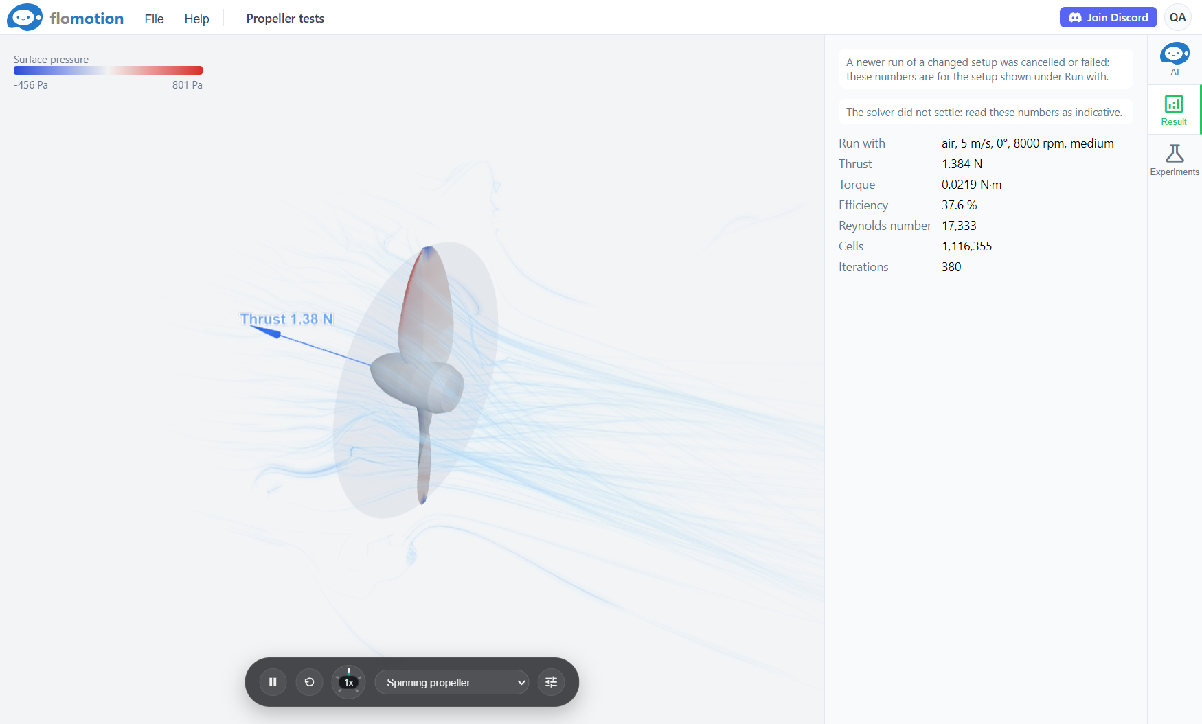
The result panel of a spinning part replaces lift and drag with the numbers that matter on a shaft: thrust, torque and efficiency. The run reports 1.38 N of thrust, 0.022 N·m of torque and an efficiency of 0.38 after 380 iterations, and notes that the solver did not fully converge. A single arrow along the spin axis shows the thrust in the viewport.
Testing a boat hull
A third experiment in the project tests a 500 mm model boat hull from the flowshapes library. The fluid is set to water at 1 m/s with a Water surface at the hull's design waterline, so the hull sits 40 mm deep with its deck 24 mm above the water, and only the part below the waterline is wetted.
The quick mesh has 45,599 cells, and the solver converges after 123 iterations at a Reynolds number of about 480,000. The run reports 0.58 N of drag and a downward force of 1.81 N (shown as a lift of −1.81 N), where the water accelerating under the hull pulls it down.
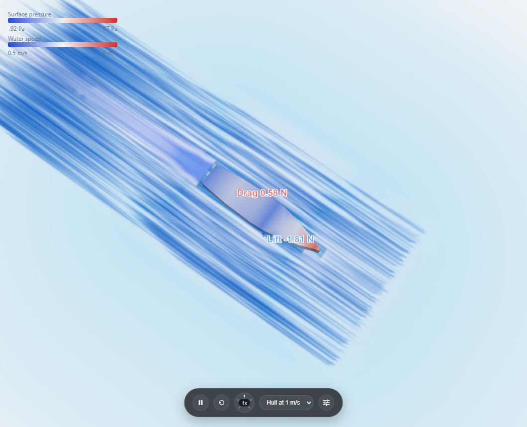
A water test with a water surface paints the surface itself with the flow just under it, the same way as a slice. The slower wake shows as a blue band on the water behind the stern. Both the painted water surface and the streaks fade out with distance from the hull, and the streak reach slider sets how far both reach. Streaks in water are drawn a deeper blue than in air.
Working with the agent and cost
A question in the chat such as how much lift does this wing make at 12 m/s? becomes a flow test. The agent sets the speed, angle of attack and flow direction, runs a quick test first, and states the time and cost before starting an accurate run. The agent then reads the numbers and the field of the finished run: it checks whether the solver converged, or whether a wing has stalled (drag rising while lift drops as the angle of attack increases). The agent handles routine setups well in practice, but it can get a flow direction or a propeller's spin direction backwards, so it is worth checking the arrows and streaks in the viewport before trusting the numbers.
Server time for flow tests is billed at 0.5 credits per minute from the same credit balance used for the agent. A quick run of a wing costs about 2 credits. Spinning parts and accurate runs take longer, and the panel shows their expected cost before Run is pressed. Current rates are on the credit costs page.
Limits
- The solver computes steady flow only. It does not capture gusts, flapping, time-varying vortex shedding, or the blade-by-blade unsteadiness of a propeller (the frozen rotor zone gives a steady average).
- A hull's water surface is a flat plane. It does not model surface waves or wave-making drag, so a fast hull's total drag in reality is higher than the reported number.
- A quick mesh puts only one cell across the thinnest parts of a shape, such as blade trailing edges, and numbers from a run that did not converge are indicative only. Results are best treated as estimates for comparing one design change against another.
- Each experiment tests one part or assembly at a time, held still or spinning about a single axis.
Summary
Wind tunnels and CFD judge wings, propellers and hulls by the forces a moving fluid exerts on them: lift, drag, thrust and torque. In FloMotion, a test bench puts a CAD part or assembly into an OpenFOAM wind tunnel, meshes the space around it and solves the steady flow. The panel and viewport show the forces, coefficients, surface pressure, flow streaks and slice planes, and the agent can set up runs and sample the flow field.
Links
- OpenFOAM, the open-source CFD toolbox used to mesh and solve the flow.
- UIUC Propeller Data Site, wind tunnel measurements and blade geometry of small propellers from the University of Illinois.
Try it yourself
Open the workspace, describe a part, and see what the agent does with it. No install, no setup. Sign-in is optional for the first run.
Start building