PCB files for fabs and KiCad
November 5, 2026
Turning a PCB layout into a physical board requires different files for different stages of the job. A fabrication house needs flat layer drawings and hole coordinates to etch and drill the bare board. An assembly line needs a part list and pick-and-place coordinates to solder the components. A mechanical CAD tool needs a 3D solid model to build an enclosure around the electronics, and a desktop EDA tool needs native project files for manual routing or archiving.
This article explains what each of those file formats contains, how fabrication and assembly houses read them, and how schematic and board files stay linked inside a project.
In FloMotion, the PCB editor stores the board natively as a KiCad file and runs KiCad's own command-line tools to generate Gerber and drill archives, assembly files, 3D models and complete KiCad projects. A board edited in desktop KiCad can also be loaded back into the workspace to continue working with the agent.
What fabrication and assembly houses read
A PCB fabrication house does not open the design file from an EDA program directly. Instead, its machines read one file per physical layer of the board: top copper, bottom copper, top and bottom solder mask, top and bottom silkscreen, and the board outline. Each file describes its layer as a collection of flat 2D shapes, such as pads, tracks and copper pours. The standard format for these layer files is Gerber, specifically Extended Gerber (RS-274X), maintained by Ucamco.
Gerber files describe flat artwork, not holes. Plated through-holes, vias and mounting holes go in a separate drill file, most often in the Excellon format, which lists tool diameters and the X and Y coordinates where each drill bit hits the board. To order a bare, unpopulated board, the Gerber files and the drill file are zipped together and uploaded to the fab.
Ordering an assembled board adds two spreadsheet files for the pick-and-place machines. A bill of materials (BOM) lists every part to be soldered, grouping identical components and giving the supplier part number for each row, such as an LCSC part number for JLCPCB. A component placement list (CPL), also called a centroid or pick-and-place file, gives one row per reference designator with its exact X and Y centre, its rotation angle and whether it sits on the top or bottom side of the board.
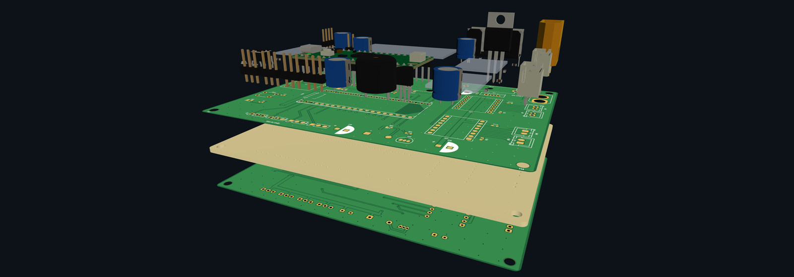
Outside the factory, two 3D formats carry the shape of the board into other tools. STEP (ISO 10303) is a mechanical CAD exchange format that stores the exact solid geometry of the board substrate and every component body on it, used for checking clearances inside a housing. GLB is the binary form of glTF, maintained by the Khronos Group, which packs a 3D mesh with materials and colours into a single file for web browsers and 3D viewers.
Exporting files from the board editor
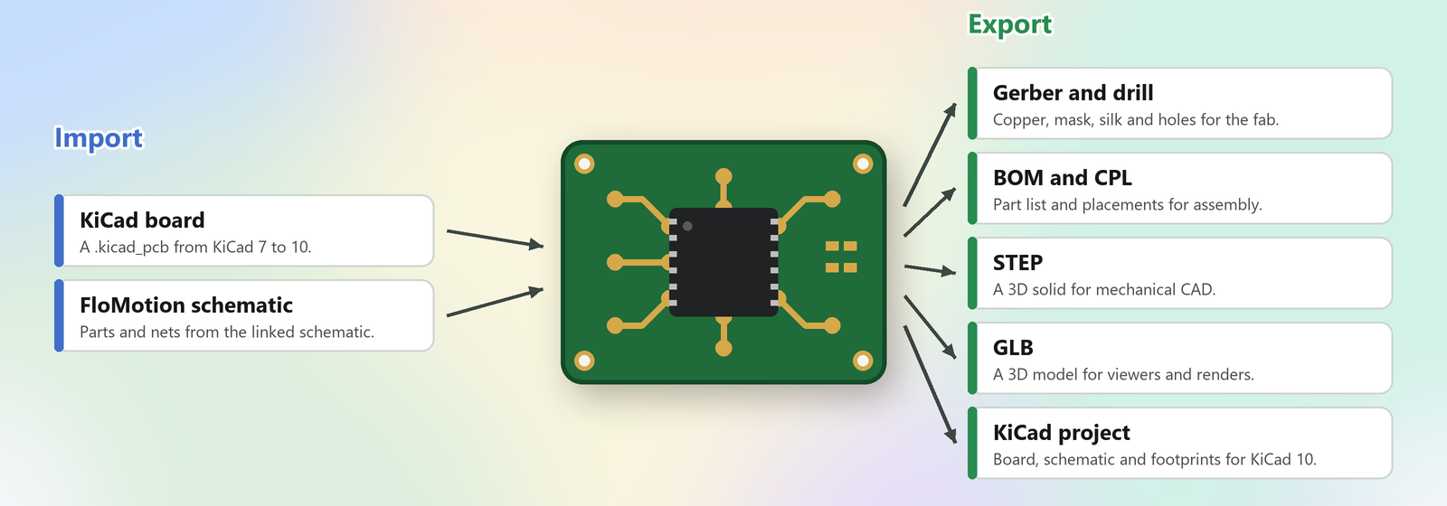
Opening the export dialog in the FloMotion PCB editor lists five outputs: Gerber and drill, BOM and CPL, STEP, GLB and a KiCad project. On the server, these exports run KiCad's own command-line tool (kicad-cli), producing the same output that desktop KiCad writes.
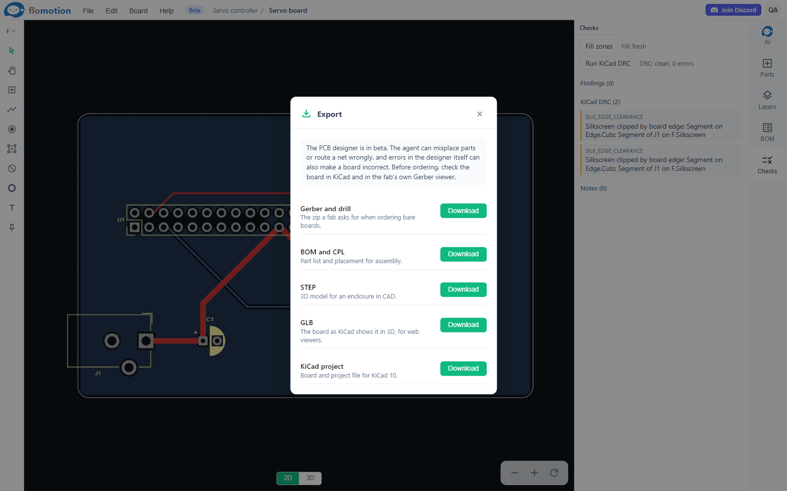
Before generating Gerber or assembly files, the editor checks that the board passes KiCad's design rule check (DRC). If the DRC reports unconnected nets or clearance violations, the dialog waits so the errors can be fixed first, though the files can be exported anyway when needed.
The Gerber and drill export packs the copper, mask, silkscreen and outline files alongside the Excellon drill files into a single zip archive ready to upload to a fab. It also renders an image of every layer so the artwork can be looked over before ordering.
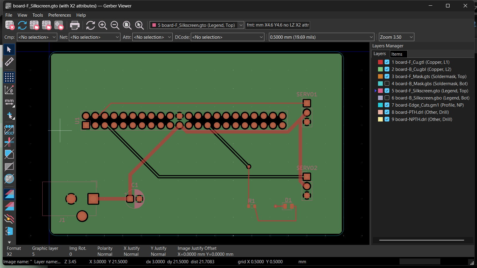
The BOM and CPL export writes two files formatted for JLCPCB's assembly service, using the LCSC part numbers attached to the components. Off-board parts and plug-in modules, such as development boards and motors, are left out of the assembly files so the fab does not try to place them.
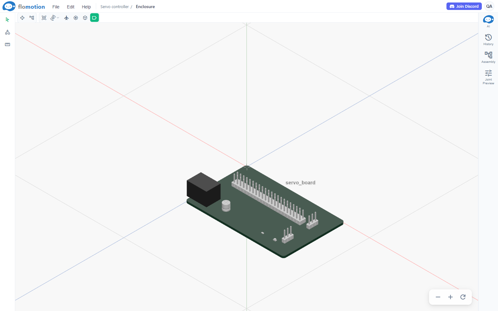
The STEP export writes a 3D solid model of the board together with all its components. That file can be imported into a FloMotion CAD workspace with its colours intact, making it straightforward to model an enclosure, line up cutouts for connectors and place mounting bosses under the board's screw holes. The GLB export writes a mesh of the board as KiCad shows it in its 3D viewer, suitable for documentation or web embeds.
Moving between FloMotion and desktop KiCad
A KiCad project is a folder of plain-text files sharing a base name: a project file (.kicad_pro), a schematic (.kicad_sch) and a board file (.kicad_pcb). Each footprint on the board stores the unique path of the schematic symbol it came from. Desktop KiCad uses those paths when running Update PCB from Schematic and when running the DRC parity check that verifies the board and schematic match.
FloMotion stores its board natively as a KiCad 10 .kicad_pcb file, so no format conversion happens on export. When the KiCad project export runs, it bundles the board file together with any 3D component models the agent drew for parts that did not have a stock 3D model, so those parts show up in desktop KiCad's 3D viewer as well.
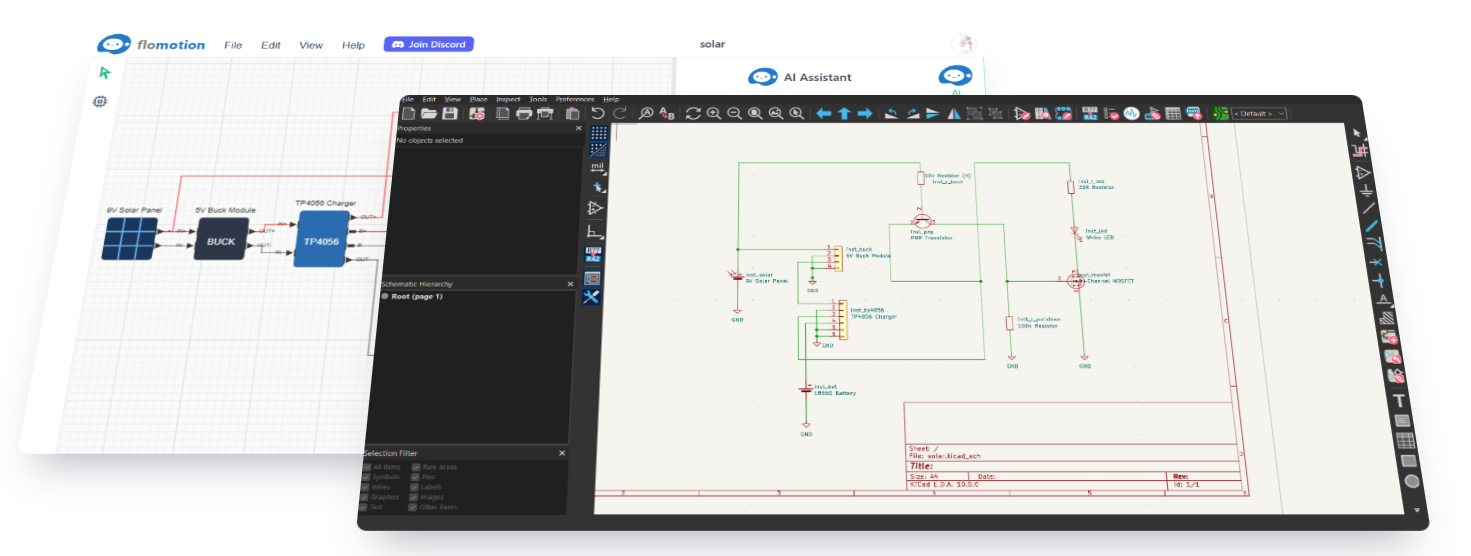
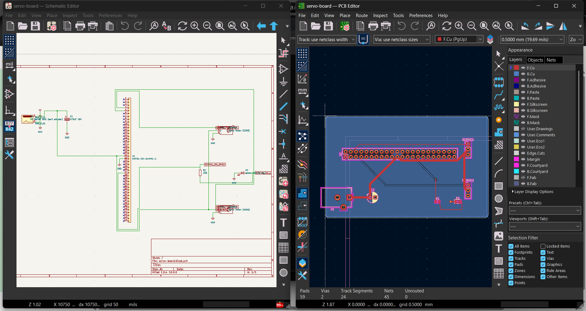
When the schematic editor exports its KiCad files under the same project name, the schematic and the board form a single KiCad project. For example, a small servo controller board with an ESP32-S3 header, two servo connectors, a barrel jack, a capacitor and an LED can be exported from both editors and opened side by side in desktop KiCad 10. Running the schematic electrical rules check (ERC) reports no errors, and running Update PCB from Schematic or the parity check finds the schematic and board in complete agreement with nothing to change.
The workflow also runs in the other direction. A .kicad_pcb file (or a zip archive containing one) edited in desktop KiCad can be loaded into the FloMotion PCB editor, replacing the current board. Copper zone fills calculated in KiCad are kept when the file loads. A designer can export a project, do manual routing or footprint adjustments in KiCad, load the .kicad_pcb file back into FloMotion and continue working with the agent.
Limitations
- The PCB editor and its exports are in beta. Always inspect the exported Gerber and drill files in the fabrication house's own previewer before placing an order.
- LCSC part numbers in the BOM are not checked against current stock or verified against the physical footprint on the board, and component rotations in the CPL can differ from JLCPCB's. Check every part in JLCPCB's placement preview before ordering assembly.
- Exported KiCad projects use the KiCad 10 file format and require KiCad 10 or newer to open on the desktop.
- Loading a
.kicad_pcbfile into the editor replaces the entire board rather than merging changes with the existing layout.
Summary
FloMotion's PCB editor stores boards as native KiCad 10 files and uses KiCad's command-line tools to export Gerber and drill archives for bare-board fabrication, BOM and CPL spreadsheets for JLCPCB assembly, STEP models for enclosure CAD, GLB meshes for viewing and complete KiCad projects that link cleanly with exported schematics and round-trip back from desktop KiCad.
Links
Try it yourself
Open the workspace, describe a part, and see what the agent does with it. No install, no setup. Sign-in is optional for the first run.
Start building