Physical controller of a virtual robot
November 19, 2026
When developing a new robotic system, it is often useful to build and test the physical controller before building the robot itself. Waiting for mechanical parts, actuators, and airframes can stall work on the control firmware and operator ergonomics. By wiring up a microcontroller and connecting it directly to a virtual scene, engineers can validate sensor filtering, control mappings, and physical feel on real hardware while the robot still exists only in CAD.
This article walks through an example of a hand-held tilt controller driving a virtual glider, and explores how the same workflow applies to any robot in a FloMotion project.
A four-wire motion controller
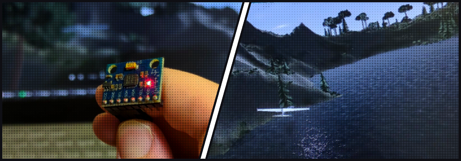
The physical setup for the demo requires only a few off-the-shelf components: an ESP32 DevKitC board, a GY-521 breakout board carrying an MPU-6050 six-axis motion sensor, four jumper wires, and a USB cable.
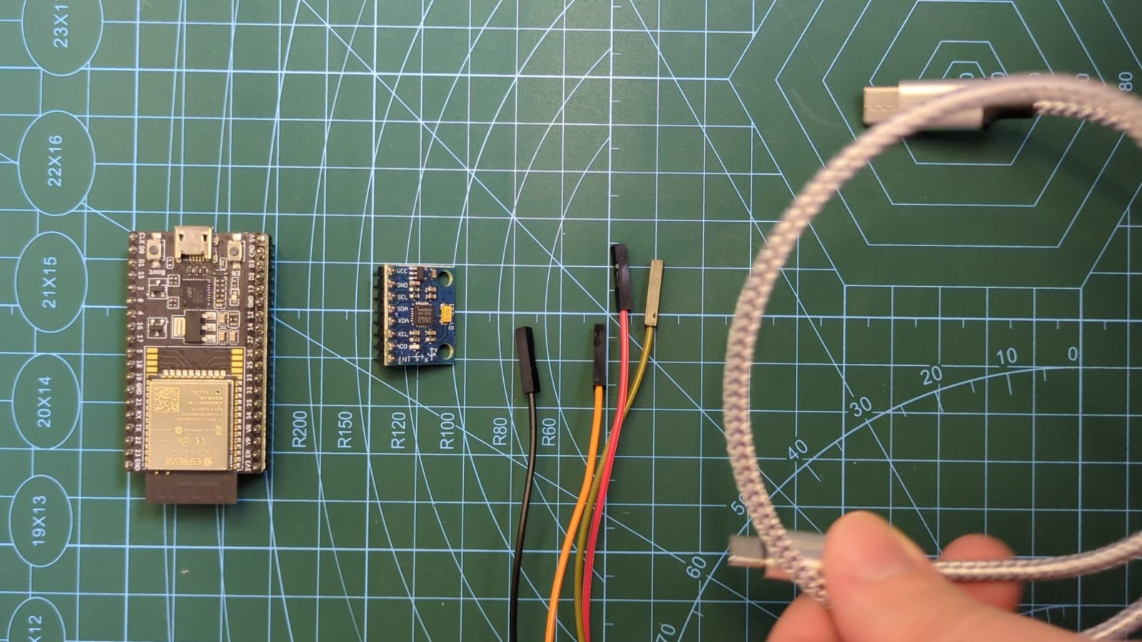
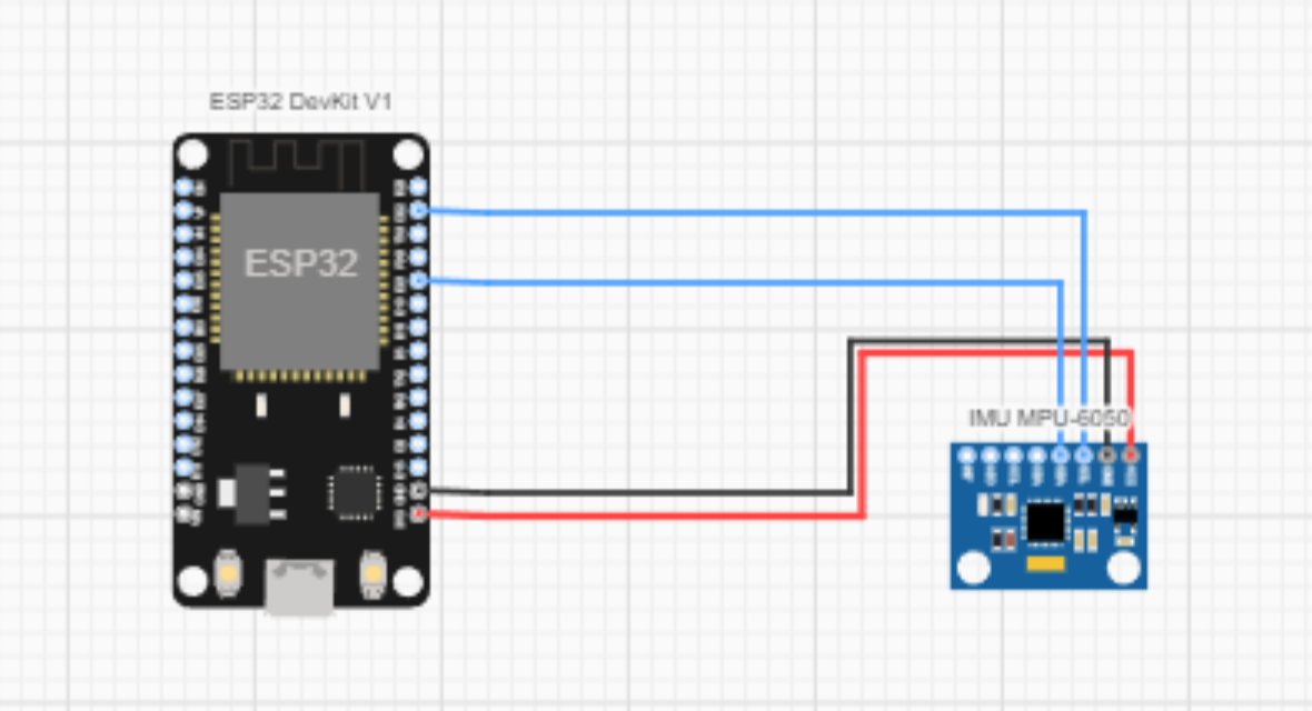
Inside the FloMotion project, the hardware schematic lives alongside the 3D scene and the firmware. The connection between the microcontroller and the inertial sensor uses standard I2C over four lines:
VCCto3V3(red)GNDtoGND(black)SDAtoGPIO21(blue)SCLtoGPIO22(blue)
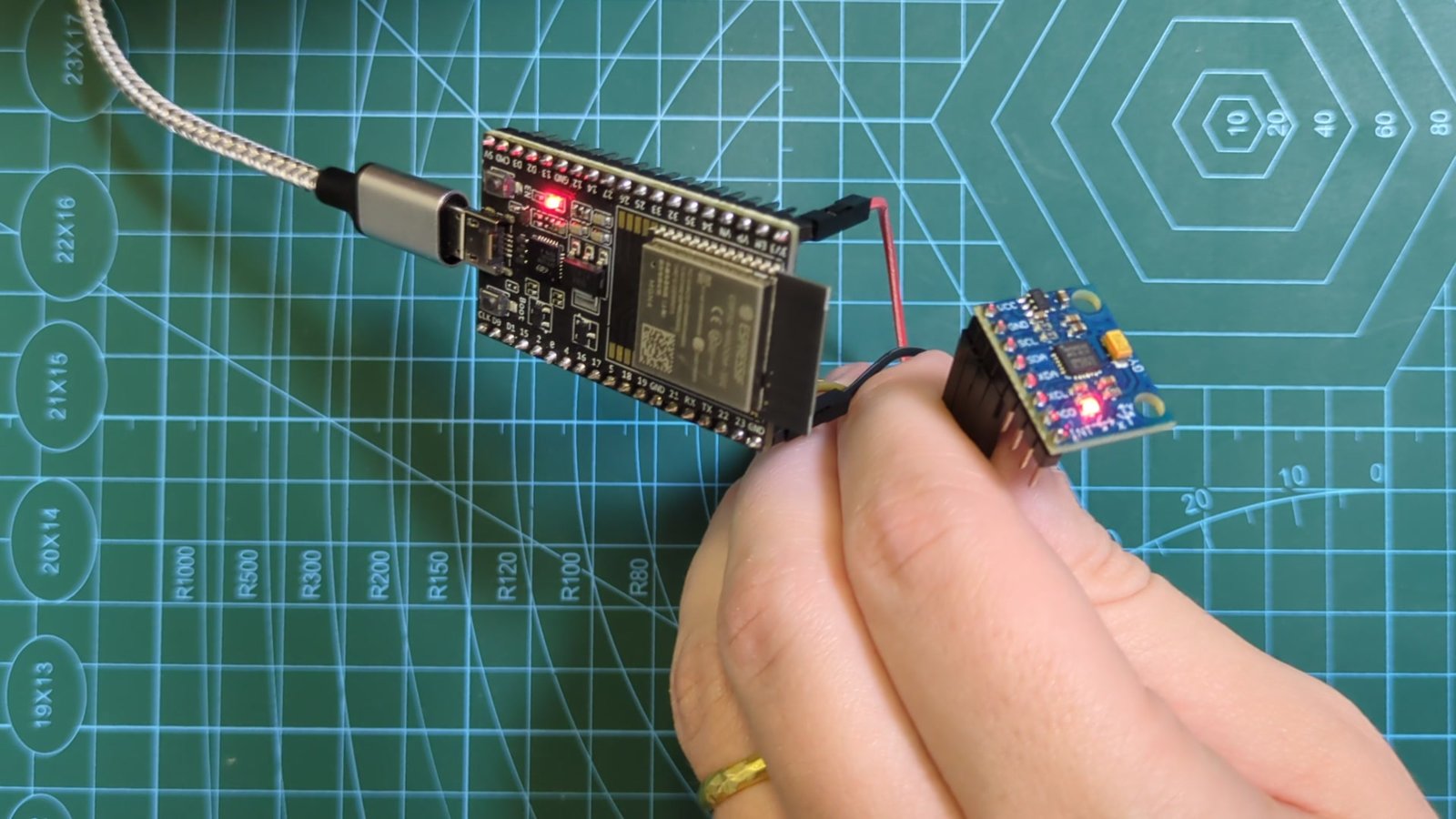
Once the four jumper wires are pushed onto the pins and the USB cable is plugged into the computer, both power LEDs light up and the hardware is ready for firmware.
Firmware and flashing from the desktop app
The firmware is written by the FloMotion agent directly in the project's firmware panel and compiled on the server using the Arduino core for ESP32. For this controller, the sketch initializes the MPU-6050 over I2C, reads the accelerometer and gyroscope at 50 Hz, computes the orientation, and prints plain text lines over USB serial:
roll=12.5 pitch=-3.2
Flashing the compiled binary and talking to the board over USB serial require the FloMotion desktop app, as a standard browser tab cannot open the raw USB serial port in this workflow. Clicking the Flash to board button uploads the firmware directly over USB. Many ESP32 development boards require the BOOT button to be held down when flashing begins; if the board does not respond immediately, the desktop app reports the reason and prompts for BOOT.
The FloMotion agent also has direct tool access to the hardware link: it can list connected boards, read serial output to verify sensor readings, and trigger a flash whenever the code changes.
A generic serial protocol for any robot
The link between the physical board and the virtual scene is intentionally generic. The desktop app does not have hard-coded knowledge of roll, pitch, or aircraft axes. Instead, it parses any name=value pairs printed by the board over USB serial, separated by spaces, commas, or semicolons, supporting up to 16 named values per line.
When the board connects to a scene, the toolbar displays the live values right next to the Board connected indicator. Each incoming line is forwarded to the scene script as a board event carrying those key-value pairs.
Because the protocol is agnostic to what the numbers mean, the exact same bridge can drive any robot in a FloMotion scene:
- Planes and drones: An IMU or a pair of analog thumbsticks streaming attitude targets or throttle commands.
- Wheeled cars and rovers: A steering potentiometer and a trigger pedal sending
steeranddrivevalues. - Robotic arms: A row of rotary encoders or potentiometers on a physical teaching pendant streaming joint angles
j1throughj6. - Legged robots: Physical switches and joysticks commanding gait velocity, body height, and yaw rate.
Flying the virtual glider
For the flight demo, the virtual scene starts from the Rocky island world template. The robot is a small glider designed in the CAD editor, with a 1 m wingspan and a mass of 350 g, similar to a light RC plane.
The scene script, also generated by the agent, listens for the board event and maps the incoming sensor angles to the glider's flight path:
rollmaps directly to the glider's bank angle, clamped up to 35 degrees.pitchis scaled by0.7to control climb or dive, also clamped up to 35 degrees.
Because the control gains, clamping limits, and axis assignments live in the scene script rather than the C++ sketch, tuning how the glider responds does not require reflashing the ESP32. Adjusting a multiplier or swapping an axis is a quick script edit—either by hand or by asking the agent.
To make flying from the laptop screen feel natural, the scene uses the chase camera mode. Alongside free, look at, follow, and third person modes, the chase camera stays behind the glider and tilts with its bank and pitch a third of a second late, giving a visual sense of turn rate while allowing the scroll wheel to zoom in and out.
Current scope and limitations
While building a physical controller first speeds up hardware and software integration, it is helpful to keep the current boundaries of this setup in mind:
- Desktop app required: Opening the USB serial port for flashing and live board connections requires the FloMotion desktop app.
- One-way communication: The serial link currently flows one way, from the physical board to the virtual scene. Force feedback or telemetry back to the controller is not part of this bridge.
- Kinematic flight script: In this glider demo, the aircraft follows the board's attitude through the scene script rather than a full aerodynamic fluid simulation, and the surrounding sea does not have collision geometry enabled.
Summary
Connecting a physical microcontroller directly to a virtual scene decouples controller development from the mechanical fabrication of the robot itself. With a simple name=value serial protocol over USB, an inexpensive board like an ESP32 and an off-the-shelf sensor can drive anything from a virtual glider to a multi-axis robotic arm. By keeping schematic design, firmware compilation, board flashing, and 3D simulation inside a single FloMotion project, engineers can validate real hardware interfaces and fine-tune control mappings long before the physical robot is assembled.
Links
Try it yourself
Open the workspace, describe a part, and see what the agent does with it. No install, no setup. Sign-in is optional for the first run.
Start building