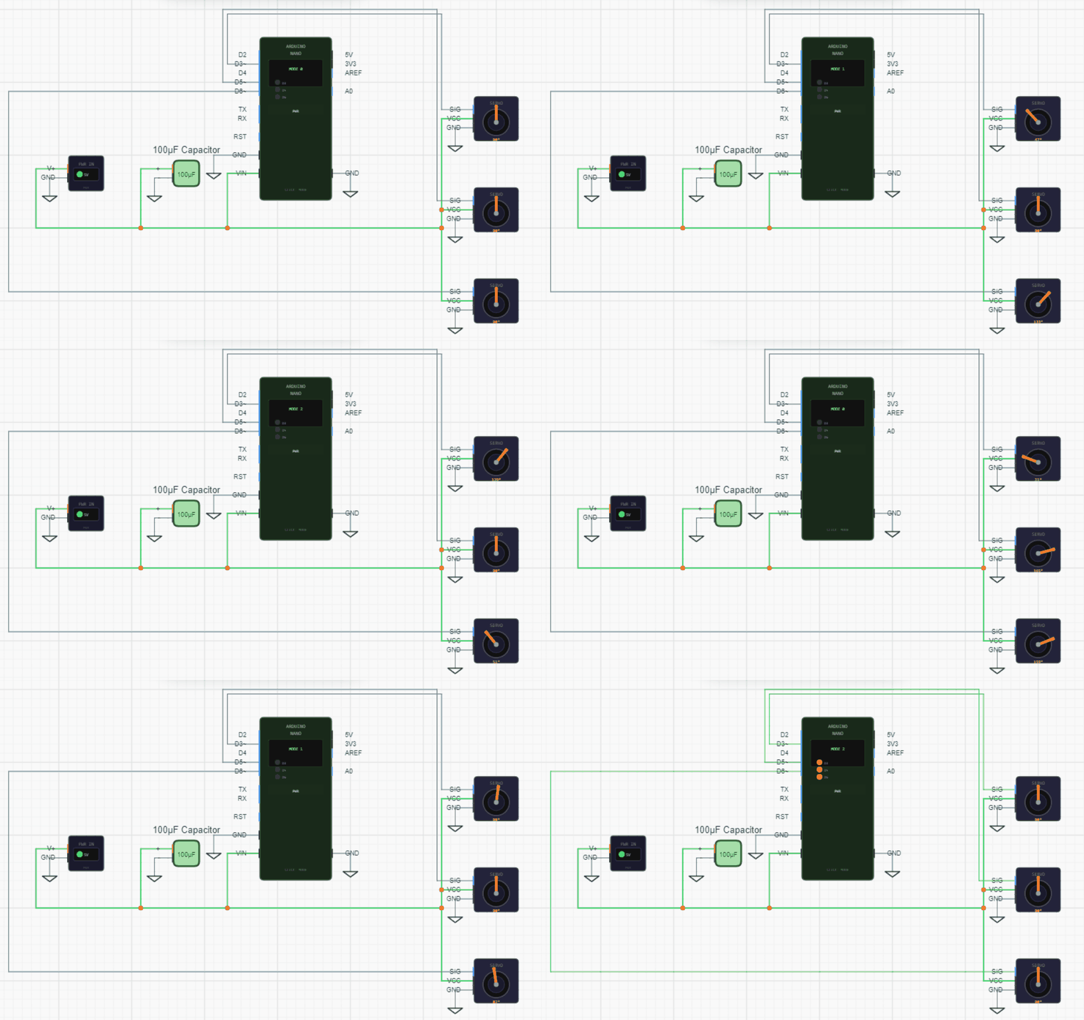
Agent-generated circuit simulation
September 1, 2026
Simulating a schematic means working out what the circuit would do if it were built, and showing that on the drawing itself. LEDs light up, servos turn, displays scroll text, and a component asked to carry more current than it can handle burns out and stops the run.
Why simulate an agent-generated circuit
An AI agent draws a schematic from a description, and the obvious question follows: is it right?
A schematic gives little away. A wire on the wrong pin looks exactly like a wire on the right pin, and a ground connection that was never made leaves nothing to notice. Reading the drawing back only confirms it matches what the agent meant, not that the intent was right.
Running the circuit is a better test, and the agent can run it unprompted: simulate, press the buttons, see what happens, fix what did not work. What that earns is confidence the design will behave on a breadboard the way it behaved on screen: parts in the right order, power and ground reaching everything, nothing overloaded.
The ceiling is worth naming. A simple simulation confirming a circuit is wired correctly and responds to input is well within reach. An elaborate one is not: a playable game across a microcontroller, a controller and a display, simulated faithfully enough to prove the firmware, is a different problem. Connectivity and basic behaviour, yes. A complete product, no.
How it works
This needs two things: a description of how each component behaves, and a way to work out the voltages everywhere in the circuit.
Resistors, capacitors and power sources need no description. The solver handles them from their values alone. Everything else gets a behavior model, a small program the agent writes: init sets up what the component remembers, build describes how it is drawn, and step runs once per tick and decides what it does.
step reads the voltage on each pin, takes any user interaction, and returns what to push back onto its pins. Those outputs come in three forms: drive a pin to a voltage through an output resistance, draw a current, or connect two of its own pins through a resistance. A 9 V battery drives its positive terminal through a small internal resistance. A closed pushbutton connects its two pins through 0.02 Ω. An LED connects anode to cathode through a small resistance plus a fixed offset for its forward voltage.
Between component steps, a solver takes all of that and works out the voltage on every net, many times a second. Since the code is generated rather than reviewed, models run sandboxed, with no access to the network or the page around them.
Components also carry electrical ratings per pin, a maximum current and a safe voltage range, which is what turns a wiring mistake into a visible failure rather than a circuit that quietly pretends to work.
Compared to SPICE
SPICE is the standard family of circuit simulators, with ngspice, LTspice and PSpice among the common ones. It works at the device level: a transistor is a set of equations describing how the silicon behaves, with numbers measured from real parts. That is what engineers reach for when checking an analogue design in detail.
This works a level up, usually called behavioural simulation. A transistor here is a short function that looks at the voltages on its three pins and decides whether to conduct, roughly the way a datasheet would describe it. Less precise, but it covers far more ground: anything the agent can describe in code can be simulated, including a microcontroller running program logic, which SPICE does not attempt at all.
The circuit is solved differently too. Rather than writing the network as equations and solving them directly, the engine uses relaxation: start from the current voltages and refine them until they settle. Cheaper per tick, and fast enough to run interactively.
So the two are not competing. SPICE answers what the voltage at a point will be. Behavioural simulation answers whether the circuit does roughly what it was meant to. For analogue design work, transistor biasing or filter response, SPICE remains the right tool.
Event-driven time stepping
Advancing time in equal steps, like a video at a fixed frame rate, suits electronics badly, because different parts of a circuit operate at wildly different speeds.
Take a microcontroller driving a servo. To command an angle it sends a pulse every 20 milliseconds, accurate to a fraction of a millisecond. The servo takes about a second to swing end to end. A step fine enough to resolve the pulse is thousands of times finer than the servo needs.
So components say when they next need attention instead. The microcontroller, having started a pulse, asks for 1.5 milliseconds, because that is when the pulse should end. The servo asks for 20. The engine jumps to the soonest request and skips the empty time between. Fast signals stay accurate without making slow movement expensive, and a circuit where nothing is happening does no work at all.
Capacitors and inductors are the exception. Those change continuously rather than at particular moments, so a circuit containing them is sampled at a steady fine interval as well.
This shifts a burden onto the model, and it is the most common way a generated one goes wrong. A component that forgets to ask for its next wake-up gets run less often than it needs, and the failure is quiet: pulse widths come out wrong, counters skip, nothing announces why. So the simulation reports how often each component asked to be woken, and warns when one changes an output without having asked.
Interactive components
A component can declare that it responds to input: presses, releases, clicks, or key presses. While the simulation runs, tapping that component on the canvas sends the event to its model.
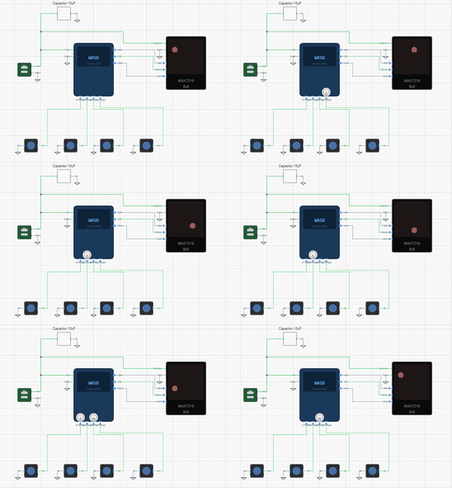
The pushbuttons above are not an animation. Pressing one sends the event to that button's model, which connects its two pins, which changes the voltage the microcontroller reads, which lights a different pixel on the display. Every link in that chain is the same one a real signal would follow.
Oscilloscope probing
Clicking a wire attaches a probe to it and opens a panel plotting its voltage over time, the way a bench oscilloscope would.
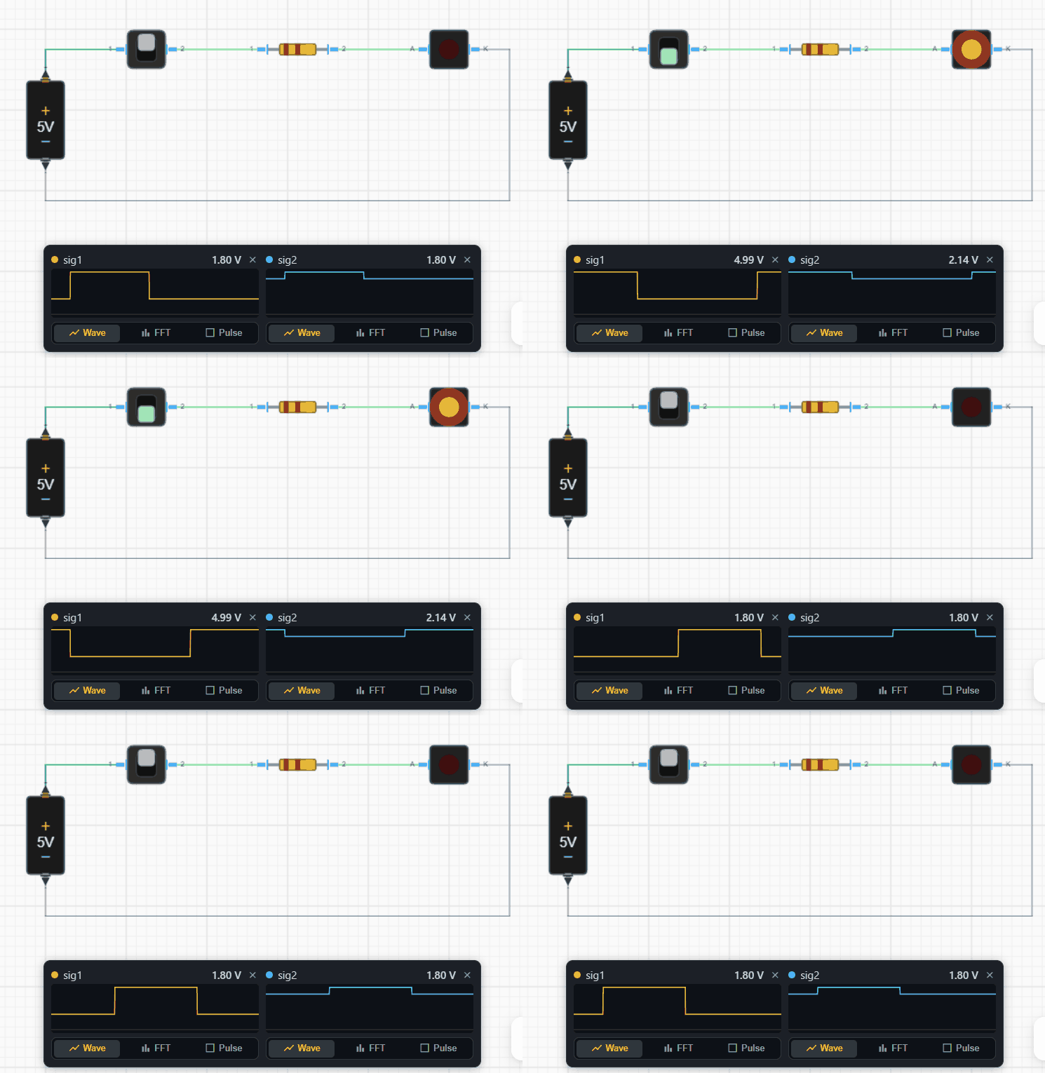
The two traces here are taken either side of the resistor. The first sits at 4.99 V, straight from the supply. The second reads 2.14 V, the forward drop across the red LED, which confirms it is conducting and the resistor is doing its job.
Each probe has three views. Wave plots voltage against time. FFT breaks the signal into the frequencies it contains, which finds the rate of a clock when the shape alone does not make it obvious. Pulse isolates one cycle and measures it: high and low levels, period, pulse width, duty cycle, frequency and edge count.
Ratings and component burnout
A component drawing more than its rated current is marked as stressed and glows. If the overload persists, or is severe enough, the part fails. Overvoltage on a pin fails it immediately. A failed component flashes, darkens, gives off smoke, stops conducting, and the simulation halts.
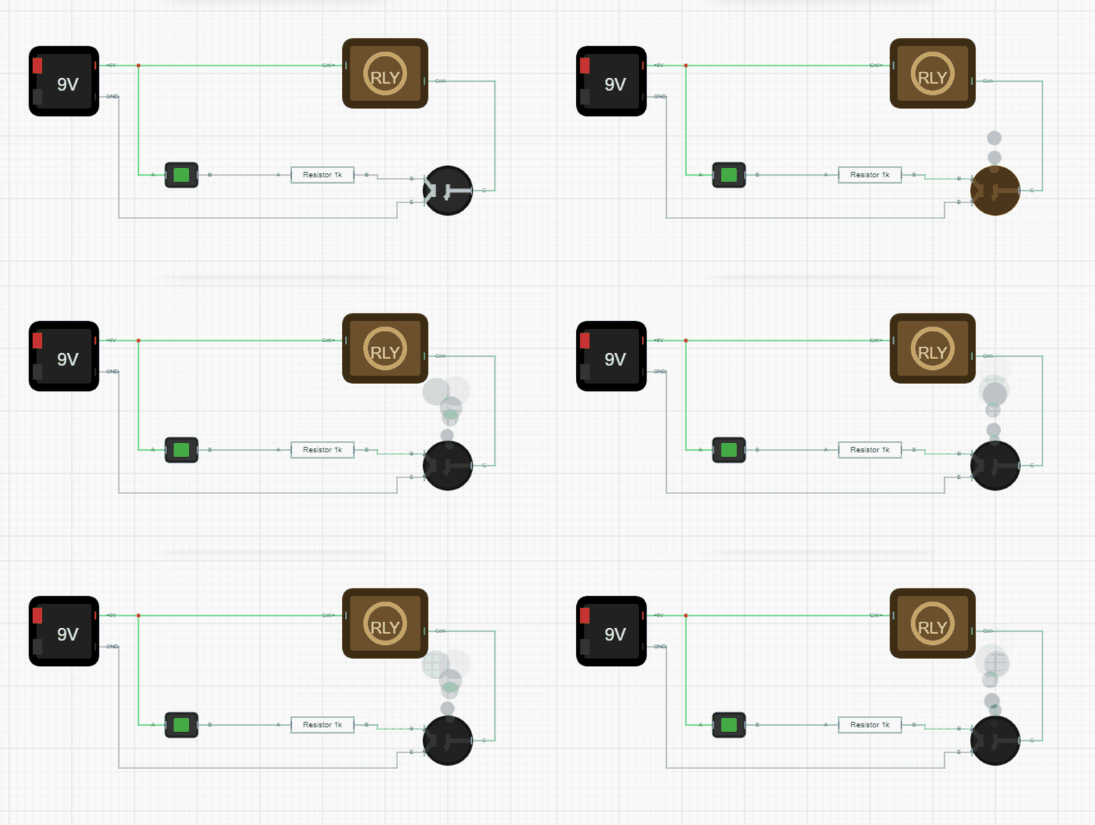
A circuit that would destroy hardware should be visibly wrong in simulation rather than quietly working. An LED straight across a 9 V battery with no series resistor draws roughly 1.4 A through a part rated for 20 mA, and in simulation it fails instead of lighting.
Ratings come from the component where specified, and fall back to a default for that kind of part otherwise. Those defaults are rough: 25 mA describes a small indicator LED, not a high-power one, so a burnout means the design is worth checking rather than that a specific part is definitely destroyed.
Running headlessly
Everything runs in the browser, on the same canvas as the schematic. There is no separate simulation window and no export step.
The agent runs the same engine without the display. After writing or changing a model it can run the circuit for a set time, press buttons at chosen moments, and read back what happened: tick counts, how often each component asked to be woken, peak current, lowest supply voltage, failures, warnings, and any messages the models logged.
That reporting matters as much as the engine. A model can be valid code, run without an error, and still produce nothing useful. Without a way to see what actually happened, the agent cannot tell a circuit that is wired wrong from a model that is written wrong, and will keep fixing the wrong one.
When a simulation will not work
Sometimes the agent sets up a simulation and the circuit does nothing, or behaves oddly. A few things help.
Ask for logs. A behavior model can print messages while it runs, and those come back with the simulation results. Asking the agent to add logging to a model that is misbehaving, then run again, usually turns a vague problem into a specific one: a state machine stuck in the wrong state, a pin voltage that never rises, a counter that never advances.
Try a stronger model. Writing a behavior model is ordinary programming, and the harder cases reward a more capable model. If the agent is going in circles, switching to one of the larger models in the picker and asking it to debug the simulation is often enough. Debugging a subtle timing problem is a different task from writing a first draft.
Say what should happen. "The LED should blink twice a second, it is staying on" gives the agent something to check against. Without a stated expectation it can only guess at which behaviour was intended.
If none of that helps, the limitation may be in the simulation engine rather than the model, particularly around analogue behaviour or timing. Those cases are worth telling us about, since they tend to be gaps we can close.
Limits
This catches the class of mistake that stops a circuit working at all: wiring errors, wrong logic, missing power or ground, components asked to carry more than they can. It misses everything subtler. There is no notion of electrical noise, heat, signal integrity at speed, or how a real component drifts from its ideal description.
There is also a circularity worth noting. The agent writes both the circuit and the models that judge it, so a passing simulation is not independent verification the way a bench test is. Misunderstand a part, and the model can inherit the same misunderstanding. What simulation reliably catches is the gap between what the agent meant and what it drew, which is where most errors live. What it cannot catch is a wrong idea applied consistently to both.
So a failing simulation is strong evidence something is wrong. A passing one means the circuit is wired the way it was meant to be, and is worth building and testing. It does not mean the design is proven.
Try it yourself
Open the workspace, describe a part, and see what the agent does with it. No install, no setup. Sign-in is optional for the first run.
Start building