Agentic CAM: AI-generated G-code for CNC manufacturing
May 31, 2026
Can I use FloMotion to generate 3D milling paths from a 3D CAD model?
FloMotion supports agentic CAM through chat prompts. After designing the part in the CAD workspace, the agent takes a description of the milling operations (which features to cut, with which tool, at what feed and depth), writes a CAM program, runs it through a CAM engine, and renders the resulting toolpath over the part. The result can then be exported to G-code, which describes how the CNC machine head will move to create the part.
2.5D milling works well in practice: profiles, pockets, slots, simple drilling on prismatic parts. True 3D surfacing (ball-nose strategies on curved surfaces) is supported, but strategy quality varies and the output is worth reviewing more carefully.
The rest of this article describes the workflow, what to specify in the prompt, and what to verify before cutting.
How CAM differs from slicing
Most AI CAD workflows today target 3D printing, which is additive: material is laid down where the part should exist. The part is described to the agent, the geometry is built, the result exports to STL, gets sliced, and goes to the printer. The slicer figures out the toolpath, because an FDM printer only needs to know where to extrude plastic in 2D layers.
CNC manufacturing is subtractive: material is removed from a block of stock by a rotating tool with defined geometry. The toolpath is not a side effect of slicing; it is the design output. Each feature gets a specific operation: profile, pocket, drill. Each operation has a tool, a feed rate, a depth of cut. The resulting G-code has to match a real machine and a real piece of stock.
A slicer takes a closed mesh and generates per-layer extrusion paths. The inputs are the mesh, the nozzle diameter, and a few printer parameters. The slicer does not need to know anything about the geometry beyond "is this point inside the part".
A CAM program needs more. Each feature to be machined is specified along with:
- The operation: profile (cut around an edge), pocket (clear out an area), drill (point cycle), face (flatten a surface).
- The tool: diameter, type (flat end mill, ball nose, drill bit), feed rate, plunge rate, spindle speed.
- The depth strategy: total depth, step-down per pass, finishing passes.
- The target geometry: which faces or edges this operation applies to.
The output is G-code: a sequence of moves the machine executes literally. There is no slicer between the design and the toolhead.
What the agent does
The geometry prompt looks the same as it would for a 3D print:
A 90mm hexagonal coaster, 6mm thick, with a 70mm hexagonal pocket on the top face 3mm deep, and an 8mm centre hole for drainage.
The agent builds the geometry. Same loop as the 3D-print workflow up to this point.
Then comes the CAM prompt:
Write a CAM program that profiles the outside hexagonal contour and pockets both the inner hexagon and the centre hole using a 3mm flat end mill at 800mm/min feed, 1.5mm depth of cut. Generate the G-code so I can see the toolpath.
What happens behind the scenes:
- The agent loads the CAM skill.
- It writes a short Python program that references the part's geometry, defines the tool, and chains the operations.
- It runs the program through a CAM engine on the backend (ocp-freecad-cam, a Python wrapper around FreeCAD's Path workbench), which produces G-code targeted at grbl by default. grbl is the open-source firmware that runs most hobby CNC mills, routers, and lasers. Other post-processors (LinuxCNC, Marlin, Mach3, Fanuc, and others) are supported.
- The toolpath renders in the 3D viewport, overlaid on the part. Each move the tool will make, visible as a line in space.
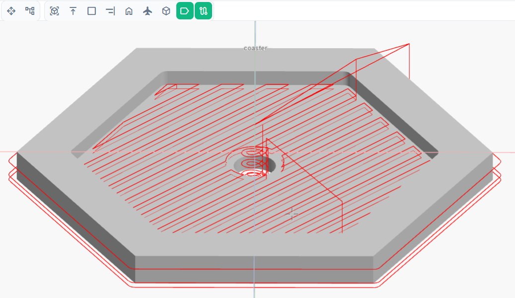
The full toolpath for the hexagonal coaster: the outside profile, the inner-hexagon pocket as parallel sweeps, and the centre-hole helix. Every red line is a move the tool will make.
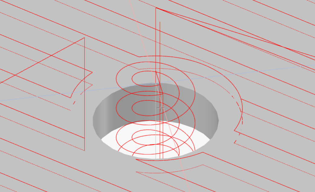
Close-up of the centre hole. The tool spirals down rather than plunging straight in, which is gentler on a flat end mill and produces a cleaner finish. The arcs are rendered smoothly because G2/G3 commands in the G-code are expanded to line segments before display.
The viewport overlay is the fastest check. If the toolpath cuts where expected, the program is probably correct. If it dives through the stock, ignores a feature, or moves in unexpected ways, the problem is visible before any G-code reaches a machine. The overlay shows the full path geometry rather than the cut order, so sequencing still has to be confirmed by reading the G-code or the agent's response.
Writing the CAM prompt
The geometry prompt and the CAM prompt can be combined into a single message, or split into two. Splitting tends to be easier when the geometry is still being iterated, since CAM scripts get cleared whenever the underlying part changes.
For the CAM prompt, the agent needs:
- Which features to machine and how. "Profile the outside", "pocket the inner hexagon", "drill the four corner holes".
- The tool. Diameter and type matter most. "3mm flat end mill", "6mm ball nose", "3mm drill bit".
- Feeds and speeds when known. "800mm/min feed, 200mm/min plunge". Defaults exist otherwise.
- Depth strategy. "1.5mm depth of cut" tells the agent how aggressively to step down.
Tools have to match the operations. A 3mm flat end mill can profile and pocket. It cannot drill an M3 clearance hole cleanly. If the prompt mixes operations the tool cannot perform, the agent may either pick a poor strategy or push back and suggest a different tool. The response is worth reading rather than skipping past.
A reasonable CAM prompt:
Profile the outside boundary, pocket the inner hexagon and the centre hole, all with a 3mm flat end mill at 800mm/min and 1.5mm depth of cut.
An over-stuffed prompt that mixes tool types:
Profile the outside, pocket the inner hexagon, and drill the four M3 corner holes with a 3mm flat end mill.
The corner holes are 3.4mm clearance. A 3mm end mill cannot drill them; it could helix-interpolate them, but that is rarely what you want. Either drop the holes or specify a drill bit.
Iterating
CAM edits are incremental like geometry edits. Useful follow-ups:
Reduce the depth of cut to 1mm for the final profile pass.
Add a 0.5mm finishing offset on the pocket.
Use a 6mm tool for the outside profile, keep the 3mm tool for the inner pocket.
The agent edits the existing CAM script and re-runs the G-code generation. The toolpath in the viewport updates when the new G-code is ready.
Multiple CAM programs can live on the same part. One for roughing, one for finishing, one with a different tool. Each shows up separately in the export dialog.
What to verify
The agent is fast at writing CAM programs but it will not catch every mistake. Things to check before cutting:
- Manufacturability of the geometry. A round tool cannot produce sharp internal corners; every inside corner ends up with a radius equal to the tool radius (1.5mm for a 3mm end mill). If the CAD has sharper corners than the tool can cut, the result will not match the design. The agent does not currently detect this. Specifying the desired internal radius in the geometry prompt (for example, "2mm internal fillets") avoids the discrepancy. A finishing pass with a smaller tool is an alternative.
- Cut order. Roughing before finishing. Inside features before the outside profile, otherwise the outside profile releases the part from the stock while interior work is still pending.
- Cut direction. Climb versus conventional milling. The agent picks defaults; preferences for a specific machine or material should be stated in the prompt.
- Plunge moves. Flat end mills do not like plunging straight down at full feed. Helical or ramped entry is safer. The agent usually picks ramped entry for pockets; profile cuts start at the edge.
- Stock alignment. The G-code uses the part's local origin. The machine has to be zeroed at the matching corner of the stock.
- Tool length and stickout. Not in the G-code, not in the toolpath preview. These have to be set on the machine.
Running the G-code in a simulator before the real machine catches the remaining mistakes. CAMotics and NCViewer both accept grbl output.
Exporting
Once the toolpath looks right:
- Open the export dialog.
- Switch to the G-code tab. It is only visible when a CAM program with generated G-code exists.
- Pick the part, then pick the CAM program.
- The file downloads, ready for a sender or simulator.
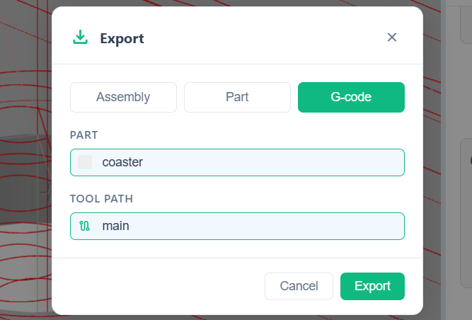
The G-code tab in the export dialog. It only appears once a CAM program has generated G-code, and lists every program on every part so the right one can be picked.
The export is the raw G-code from the CAM engine. No post-processing, no machine-specific tweaks. Machines that need different line endings, a different start sequence, or specific M-codes get the file through a sender's preprocessor or by editing the script directly.
The toolpath preview is the contract. If it looks right, the G-code is probably fine. If it does not, edit the prompt and regenerate before cutting anything.
Try it yourself
Open the workspace, describe a part, and see what the agent does with it. No install, no setup. Sign-in is optional for the first run.
Start building